Portfolio — Cover
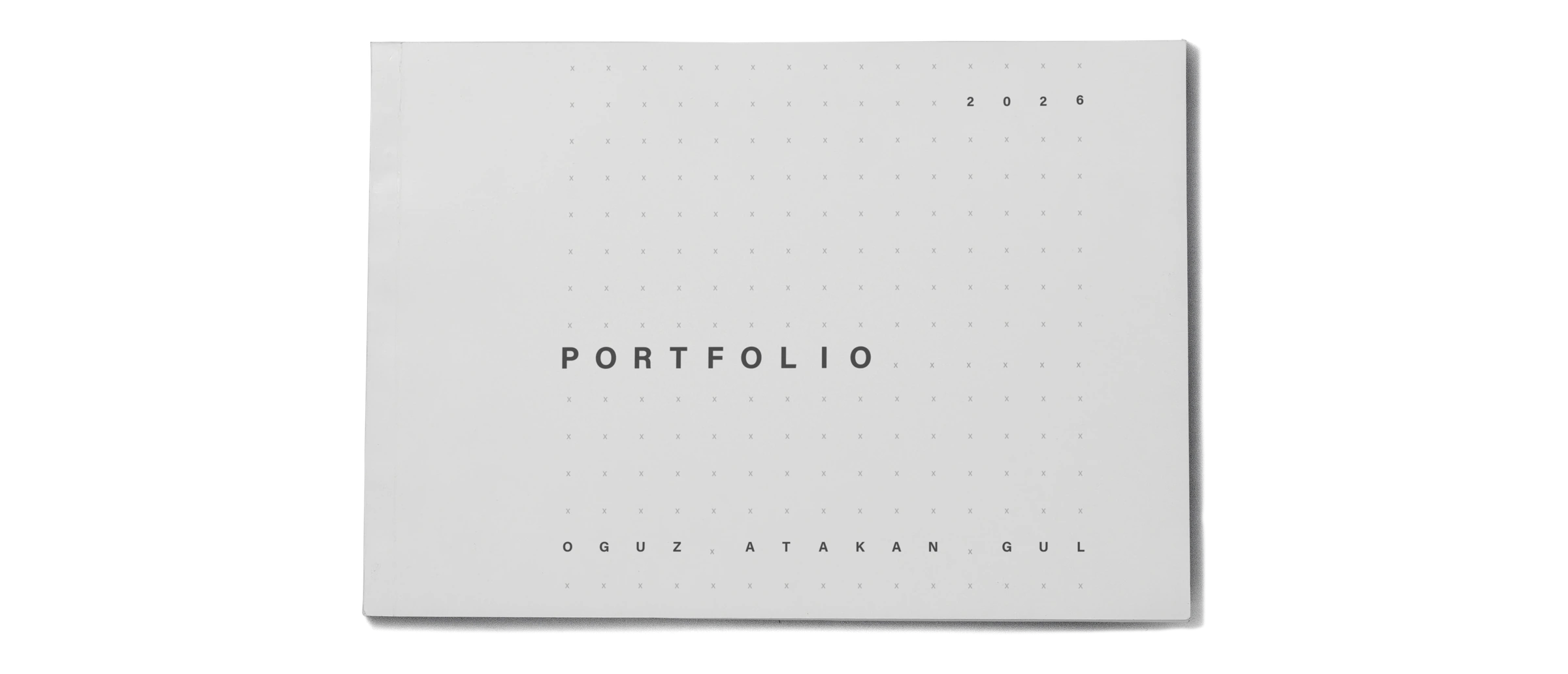
Portfolio 2026 by Oguz Atakan Gul. A pale cover with a subtle repeated cross pattern, letterspaced title and name.
PORTFOLIO. 2026. OGUZ ATAKAN GUL.
oguz atakan gul
Architect, PhD. Interior Designer, MA. Architectural Engineer, MSc.

Portfolio 2026 by Oguz Atakan Gul. A pale cover with a subtle repeated cross pattern, letterspaced title and name.
PORTFOLIO. 2026. OGUZ ATAKAN GUL.
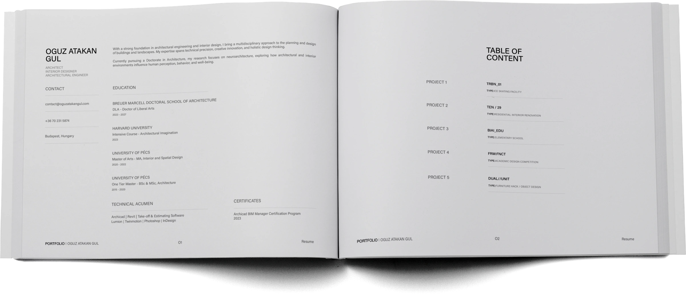
The opening spread presents Oguz Atakan Gul’s resume, neuroarchitecture research statement, education, contact information and software skills, followed by five named portfolio projects.
OGUZ ATAKAN GUL — ARCHITECT, INTERIOR DESIGNER, ARCHITECTURAL ENGINEER.
With a strong foundation in architectural engineering and interior design, I bring a multidisciplinary approach to the planning and design of buildings and landscapes. My expertise spans technical precision, creative innovation, and holistic design thinking.
Currently pursuing a Doctorate in Architecture, my research focuses on neuroarchitecture, exploring how architectural and interior environments influence human perception, behavior, and well-being.
CONTACT
EDUCATION
TECHNICAL ACUMEN
Archicad | Revit | Take-off & Estimating Software. Lumion | Twinmotion | Photoshop | InDesign.
CERTIFICATES
Archicad BIM Manager Certification Program, 2023.
TABLE OF CONTENT
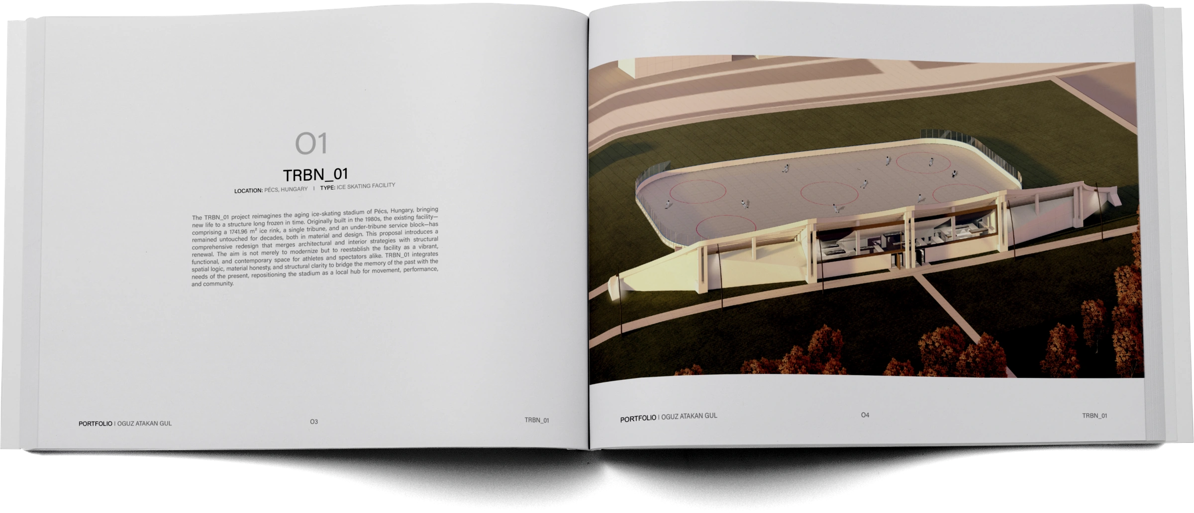
TRBN_01 proposes renewal of the ice-skating facility in Pécs, Hungary. An aerial visualization shows the long service building in front of the outdoor rink, with surrounding paths, lawn and trees.
01 — TRBN_01. LOCATION: PÉCS, HUNGARY. TYPE: ICE SKATING FACILITY.
The TRBN_01 project reimagines the aging ice-skating stadium of Pécs, Hungary, bringing new life to a structure long frozen in time. Originally built in the 1980s, the existing facility—comprising a 1741.96 m² ice rink, a single tribune, and an under-tribune service block—has remained untouched for decades, both in material and design. This proposal introduces a comprehensive redesign that merges architectural and interior strategies with structural renewal. The aim is not merely to modernize but to reestablish the facility as a vibrant, functional, and contemporary space for athletes and spectators alike. TRBN_01 integrates spatial logic, material honesty, and structural clarity to bridge the memory of the past with the needs of the present, repositioning the stadium as a local hub for movement, performance, and community.
Page 4 — Aerial architectural visualization: a long, low service building and spectator tribune border one long side of an outdoor ice rink. Glazed openings reveal rooms beneath the tribune. The rink has rounded ends and circular ice markings, and is enclosed by boards and clear screens. Paths cross the surrounding lawn, with trees at the foreground edge.
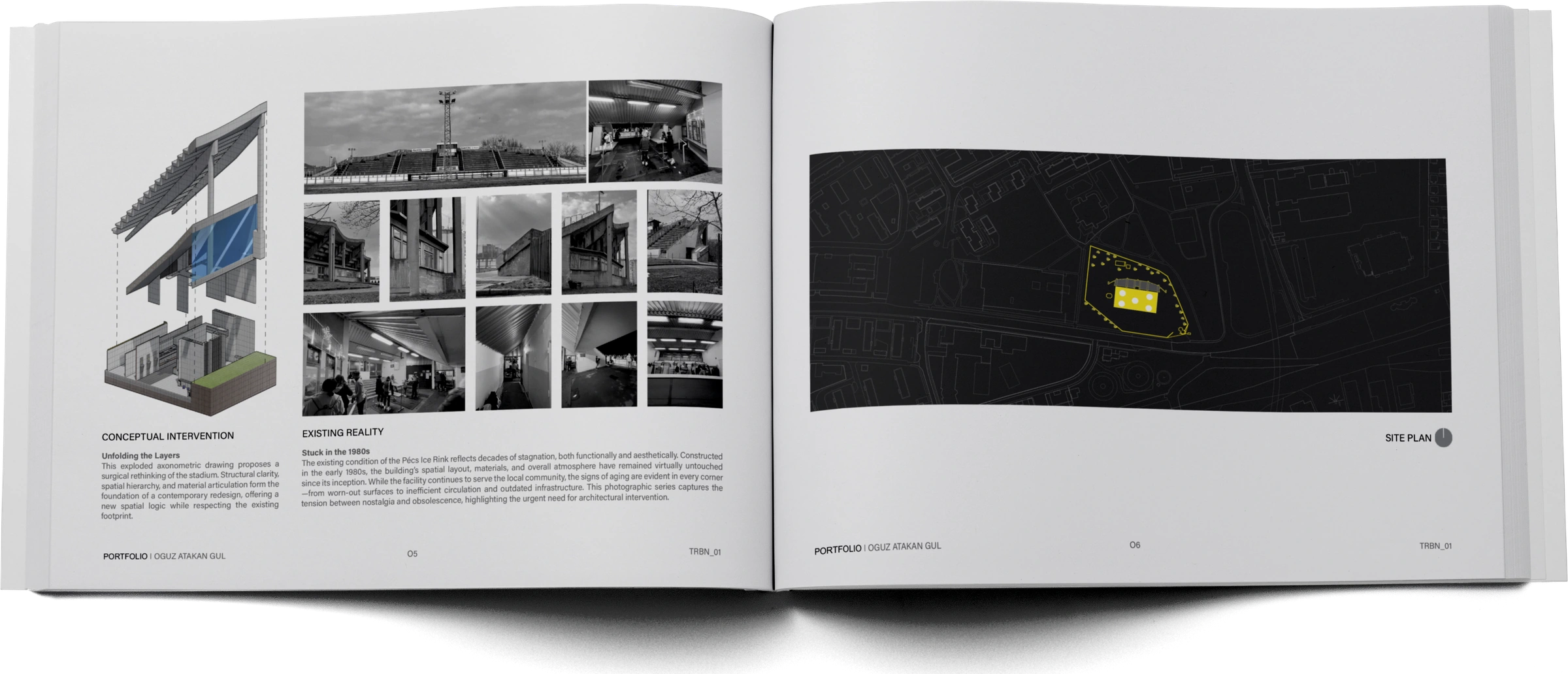
An exploded axonometric separates the tribune roof, glazed intervention and service block beside photographs of the existing rink building. The site plan highlights the rink and its plot within the surrounding street pattern.
CONCEPTUAL INTERVENTION — Unfolding the Layers
This exploded axonometric drawing proposes a surgical rethinking of the stadium. Structural clarity, spatial hierarchy, and material articulation form the foundation of a contemporary redesign, offering a new spatial logic while respecting the existing footprint.
The exploded drawing separates the stepped tribune/roof structure above, a glazed strip and concrete supports in the middle, and the ground-level service enclosure below. Dashed vertical lines align the layers.
EXISTING REALITY — Stuck in the 1980s
The existing condition of the Pécs Ice Rink reflects decades of stagnation, both functionally and aesthetically. Constructed in the early 1980s, the building’s spatial layout, materials, and overall atmosphere have remained virtually untouched since its inception. While the facility continues to serve the local community, the signs of aging are evident in every corner—from worn-out surfaces to inefficient circulation and outdated infrastructure. This photographic series captures the tension between nostalgia and obsolescence, highlighting the urgent need for architectural intervention.
The black-and-white photographic collage shows the outdoor spectator tribune, concrete exterior supports and service spaces, roof soffits, doors, bench-lined corridors and occupied changing/reception areas.
SITE PLAN — The rink and irregular site boundary are highlighted in yellow against a dark plan of surrounding roads and building footprints. A north indicator appears beside the site-plan title.
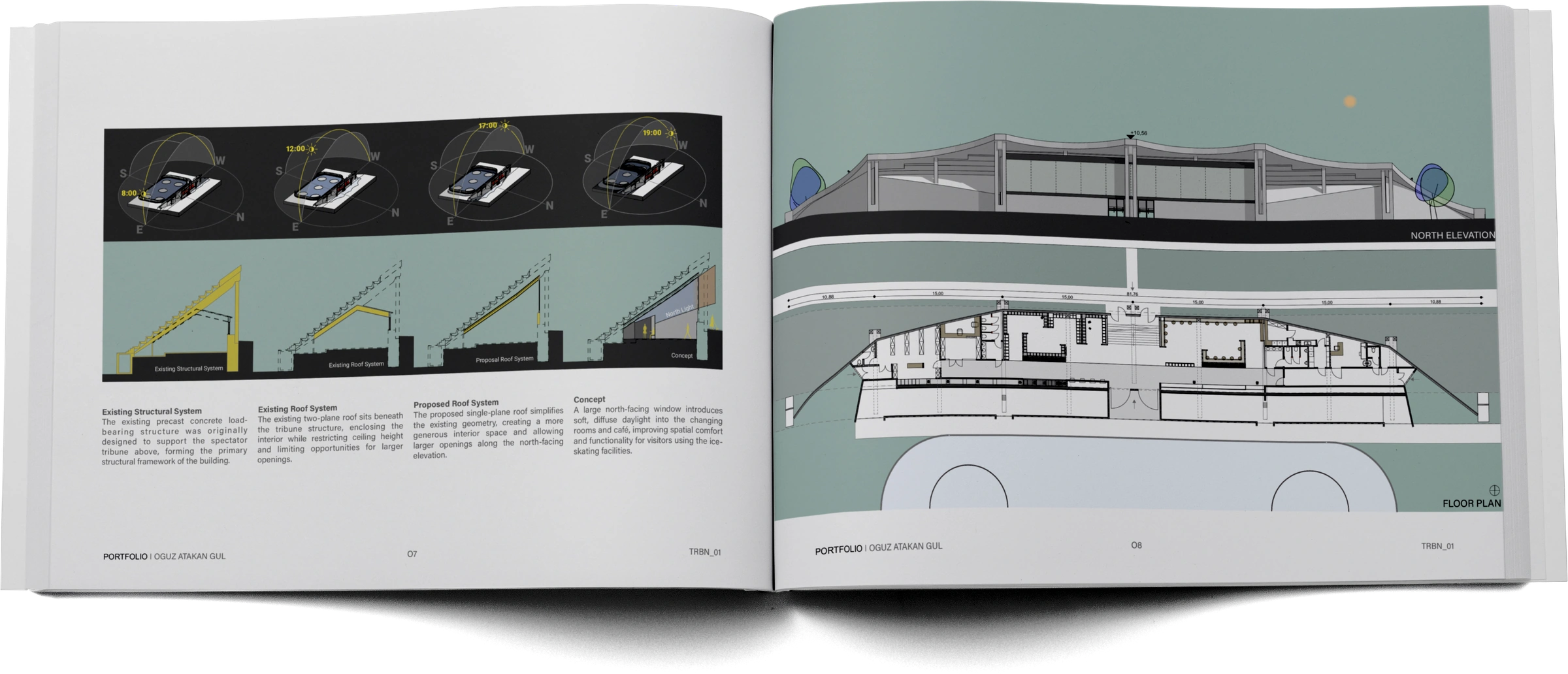
Solar diagrams and four sectional stages explain replacement of the restrictive two-plane interior roof by a single plane and a north-facing window. The facing page pairs the north elevation with the long service-block floor plan.
Solar diagrams show the building and rink with cardinal directions and sun positions labeled 8:00, 12:00, 17:00 and 19:00.
Existing Structural System
The existing precast concrete load-bearing structure was originally designed to support the spectator tribune above, forming the primary structural framework of the building.
Existing Roof System
The existing two-plane roof sits beneath the tribune structure, enclosing the interior while restricting ceiling height and limiting opportunities for larger openings.
Proposed Roof System
The proposed single-plane roof simplifies the existing geometry, creating a more generous interior space and allowing larger openings along the north-facing elevation.
Concept
A large north-facing window introduces soft, diffuse daylight into the changing rooms and café, improving spatial comfort and functionality for visitors using the ice-skating facilities.
NORTH ELEVATION — A long, low frontage follows the rising and falling profile of the spectator structure. Repeated concrete supports frame the broad glazed opening; the center high point is marked +10.56.
FLOOR PLAN — The service rooms form a narrow strip between the street-side frontage and the rink. The plan shows a central entrance, a continuous circulation zone, larger central spaces with seating and small tables, and smaller subdivided service rooms toward the ends. The rink occupies the foreground side.
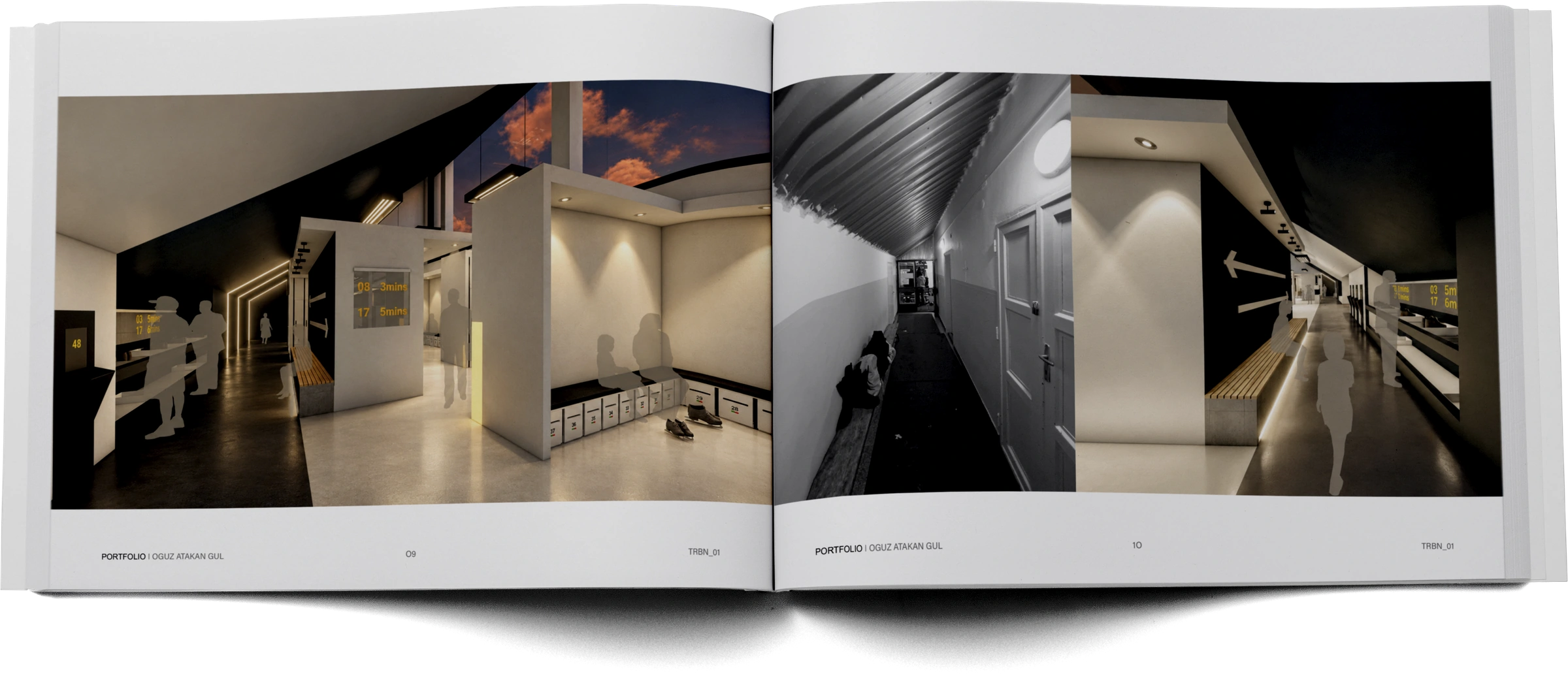
A proposed entrance and changing-space visualization is paired with an existing bench-lined corridor photograph and a proposed rink-side passage. Dark circulation surfaces contrast with bright changing areas and linear lighting.
Page 9 — Proposed interior visualization: the rink-side circulation route has a dark floor and dark wall with a line of glowing angular light frames. Beside it, pale walls and a pale floor define changing alcoves with low storage lockers, benches and skate-changing visitors. High glazing rises beneath the tribune structure, with rectangular suspended lights and a wood-slat bench.
Page 10, left — Existing black-and-white corridor photograph: a narrow passage has a low ribbed sloping ceiling, doors along the right and a bench along the left.
Page 10, right — Proposed corridor visualization: a long wood-slat bench and illuminated base run beside a dark wall with opposing directional arrows. The rink railing and displays are opposite; the route opens into a brighter interior farther ahead.
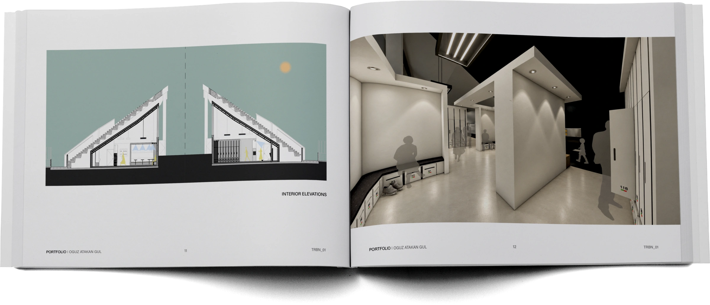
Two transverse interior elevations show the wedge-shaped spaces beneath the tribune and the inserted horizontal interior ceiling. The facing visualization shows low bench lockers, tall lockers and lit partition alcoves.
INTERIOR ELEVATIONS — Two mirrored transverse drawings show the steep stepped spectator tribune outside and the shallow single-plane interior roof below. Horizontal suspended lights sit over changing and café spaces. The left drawing includes stools and a wall counter; the right includes tall lockers and figures for scale.
Page 12 — Proposed interior visualization: low storage lockers beneath a dark continuous bench line the left wall; tall narrow lockers line the right. Pale freestanding partition walls and lit overhead edges form changing alcoves below the high dark tribune soffit. Suspended rectangular light fittings and the broad pale floor connect the spaces.
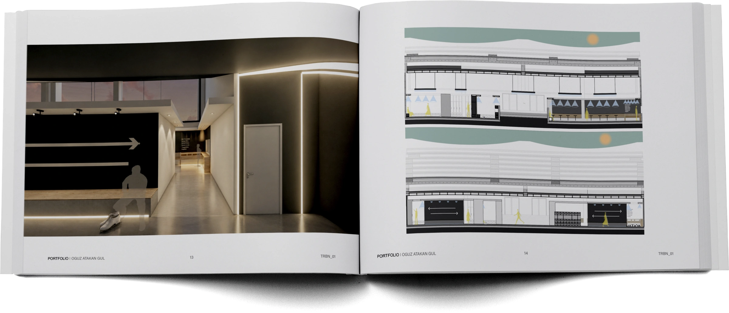
An interior visualization uses opposing arrows, bench lighting and vertical light strips to distinguish a rink-side passage from the bright café approach. Two long interior elevations show the counter, lockers, doors and repeated lighting.
Page 13 — Proposed interior visualization: a wood-slat bench sits against a dark wall bearing two large opposing arrows. A bright central passage leads toward a café counter. A gray door at the right is framed by vertical white light strips, while high glazing and recessed lights sit beneath the spectator structure.
Page 14 — Two longitudinal interior elevations show the long sloping structure and continuous ceiling line above the rooms. The upper elevation includes doors, a glazed section and a café wall counter with stools; the lower elevation includes directional arrow graphics, doors, low lockers and human figures indicating scale.
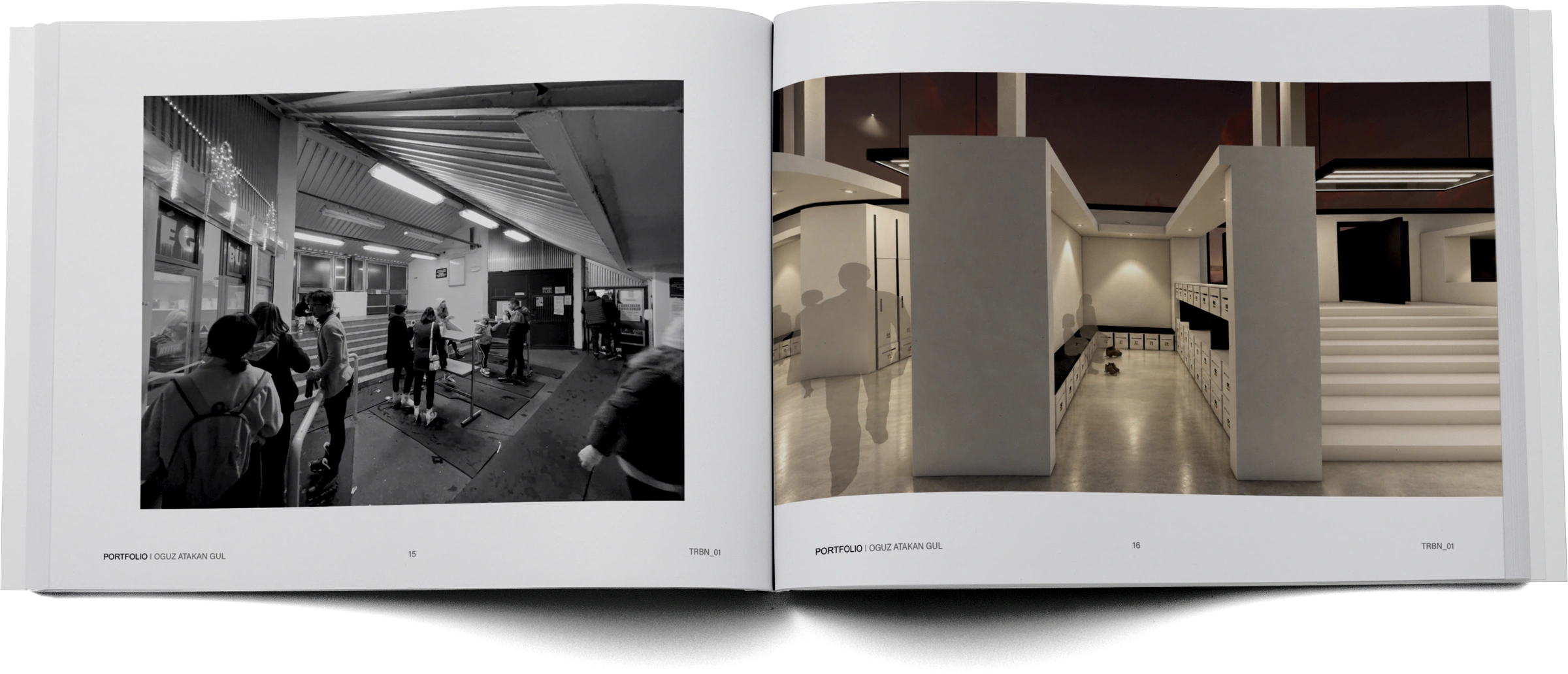
An existing occupied changing-space photograph is paired with a visualization of organized locker alcoves beside a broad stair. The comparison contrasts the original low ribbed ceiling and worn floor with pale partitions, continuous benches and overhead daylight.
Page 15 — Existing black-and-white interior photograph: visitors change into skates in a room with a low ribbed sloping ceiling, roof beams, windows, steps and small tables. Dark mats cover portions of the floor.
Page 16 — Proposed interior visualization: pale partitions and overhead frames define small locker and bench alcoves. Low numbered lockers wrap the central changing area, while taller lockers stand at the left. A broad white stair rises beside the alcove on the right, beneath high glazing and suspended rectangular lights.
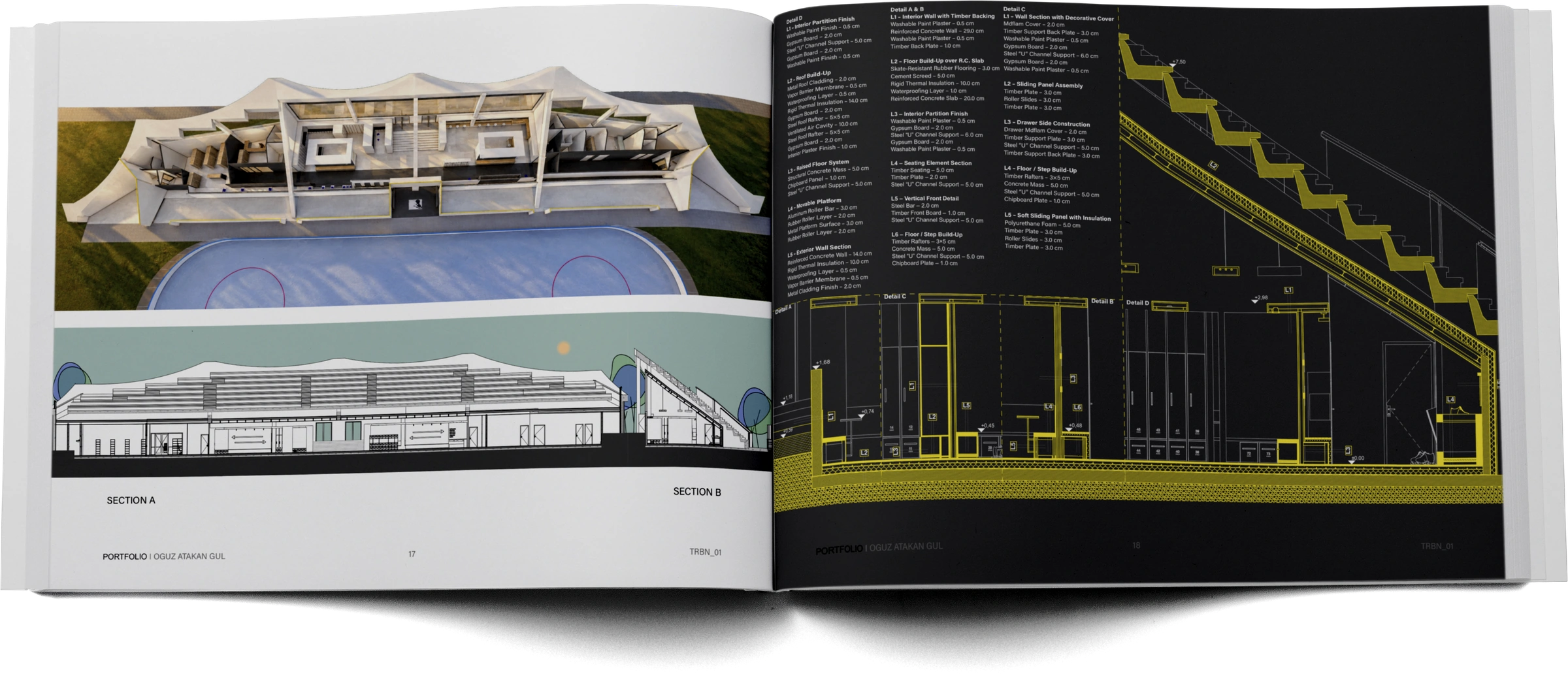
A roof-open cutaway and sections expose the service spaces beneath the spectator tribune. The opposite page expands Details A–D into wall, roof, floor, seating, drawer and sliding-panel build-ups, drawn in yellow on black.
SECTION A / SECTION B — A roof-open oblique cutaway shows the service rooms, changing alcoves, central access and continuous rink-side route within the long building. Below, longitudinal and transverse sections relate the inserted interior spaces and ceiling to the repeated concrete tribune structure above.
The technical drawing on page 18 shows the stepped tribune over a sloping layered roof and a full-height interior section, with enlarged wall/furniture details labeled A, B, C and D. The layer specifications below follow the labels printed on the sheet.
Detail A & B
Detail C
Detail D
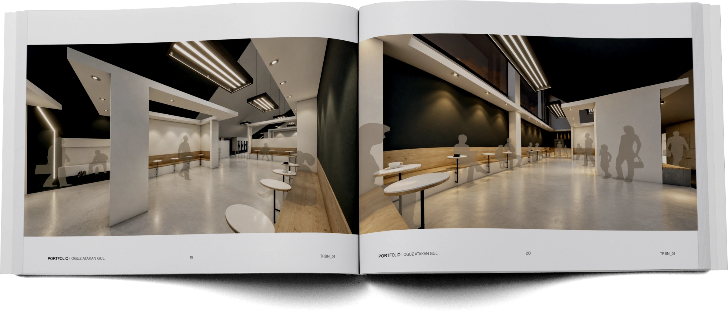
Two opposing interior views show continuous timber bench seating, small white oval tables and freestanding pale partitions under the tribune. Dark upper surfaces, high glazing and suspended rectangular lights frame the shared café and circulation space.
Page 19 — Proposed café/changing interior: a continuous timber bench with small oval white tabletops runs along the right wall. Pale rectangular frames separate open seating and changing alcoves. The long central pale floor connects these areas beneath suspended rectangular light fittings and dark sloping upper surfaces.
Page 20 — Reverse interior view: the timber bench and oval tables run along the left, against a dark wall. Freestanding pale walls and overhead frames divide the long hall without closing its circulation route. High glazing, recessed spots and suspended light fittings illuminate the space.
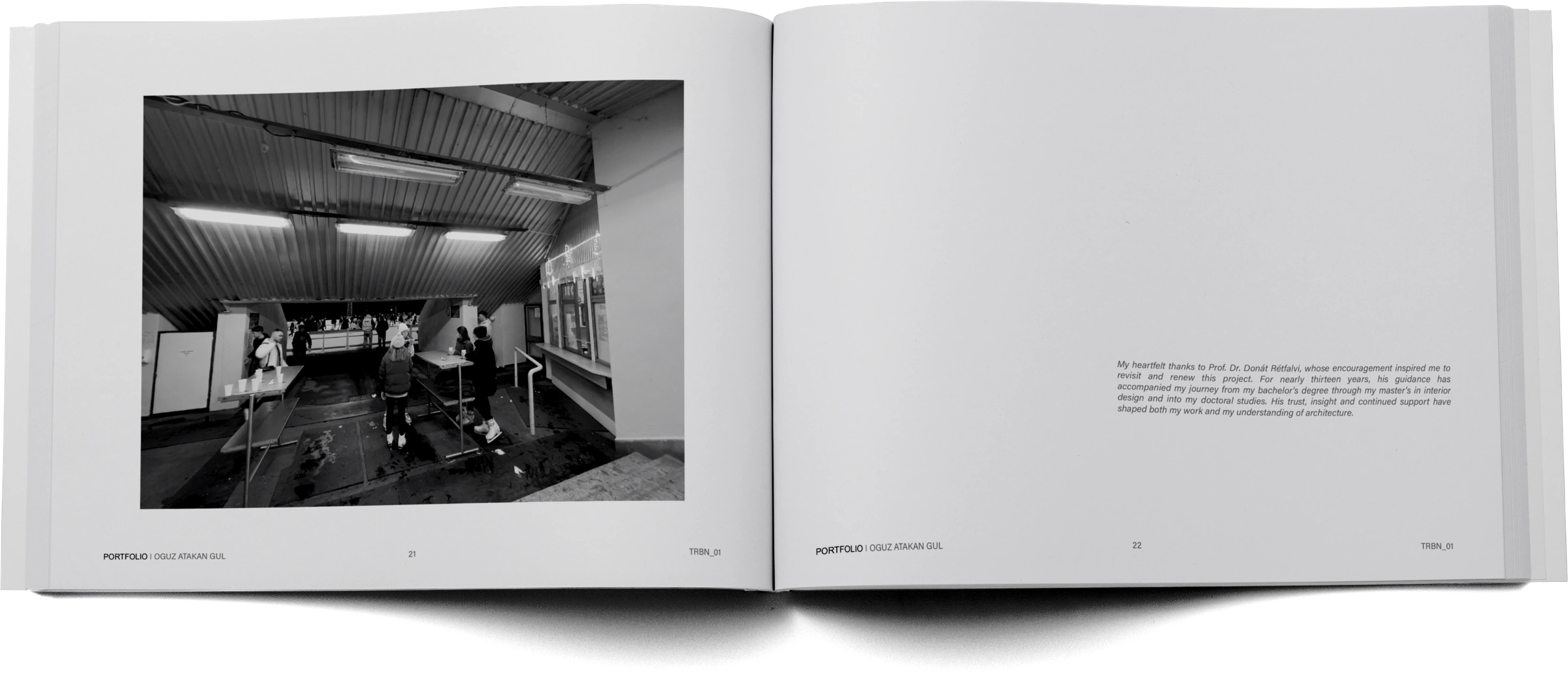
A black-and-white photograph records the existing skate-changing area. The closing page thanks Prof. Dr. Donát Rétfalvi for nearly thirteen years of guidance from bachelor’s study through doctoral work.
Page 21 — Existing interior photograph: visitors stand at small tables in the skate-changing area beneath a low ribbed ceiling and exposed beams. Long fluorescent fittings hang overhead; windows and a bench line the right side, and mats cover parts of the floor.
My heartfelt thanks to Prof. Dr. Donát Rétfalvi, whose encouragement inspired me to revisit and renew this project. For nearly thirteen years, his guidance has accompanied my journey from my bachelor’s degree through my master’s in interior design and into my doctoral studies. His trust, insight and continued support have shaped both my work and my understanding of architecture.

The globe could not be loaded. You can retry or view all buildings.
Drag to rotate the globe. Scroll the mouse wheel or pinch to zoom. Double-click or double-tap to zoom in or fit the globe. Use arrow keys to rotate, plus and minus to zoom, and Home to reset. Select a marker to view photographs, or choose View all buildings to browse the gallery.


